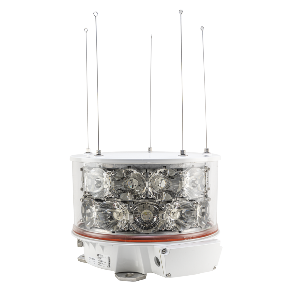
L420EX-W-06-U05
Explosion proof LED marine light (6 NM) for decentralised systems
Certified marine light for zone 1 and 2 gas hazardous areas marine light providing 6 nautical mile white omnidirectional visual coverage for offshore structures. The design, with long life LEDs, makes the product ideal for harsh environmental conditions and long maintenance intervals.
Key features
- Reliable marine navigation light, low cost of ownership and low power consumption
- Suitable for Zone 1 and Zone 2 areas with gas explosion hazard
- Suitable for a 12 VDC or 24 VDC power supply*
- Wireless synchronisation via GPS possible (separate synchronisation cable not required)
- Light intensity including 25% service factor as per IALA E-200 (2008)
- Offshore coated, lightweight, corrosion free, seawater, UV and humidity resistant light alloy base
- Stainless steel mounting facilities to prevent contact corrosion problems
- Integrated Ex e connection box
- Very low power consumption due to efficient optical design
- Anti bird spikes (to prevent bird fouling)
Standards/Certification
- Cenelec EN 60079-0, EN 60079-7 EN 60079-18 and EN 60079-28
- Sira 12ATEX3060X; ATEX Ex ll 2G Ex e mb op is IIC T4 Gb
- IEC 60079-0, IEC 60079-7 IEC 60079-18 and IEC 60079-28
- IECEx SIR 12.0025X; Ex e mb op is llC T4 Gb
Performance characteristics
- Flashing white light, Morse code ‘U’ every 15 seconds
- Effective intensity: 180 cd minimum (equals 6 NM at ATF=0.74)
- Horizontal beam coverage: 360°
- Vertical beam profile: 2.5° FWTM minimum
Physical characteristics
- Dimensions (L x W x H): 447 x 416 x 314 mm
- Weight: 21 kg
- Degree of protection: IP66
- Operating temperature range: -40°C to +55°C
Electrical characteristics
- Operating voltage: 11 – 30 VDC*
- Power consumption: Approx. 1.2 W average during operation at specified flash character
- Connection details: max. 4 mm²; one M25 cable gland entry
- Earth connection: internal max. 4 mm² and external M5
System design, control and Monitoring
- *Power, control and monitoring functions by a small, locally mounted control box
- Synchronisation via GPS or optional hard wired


