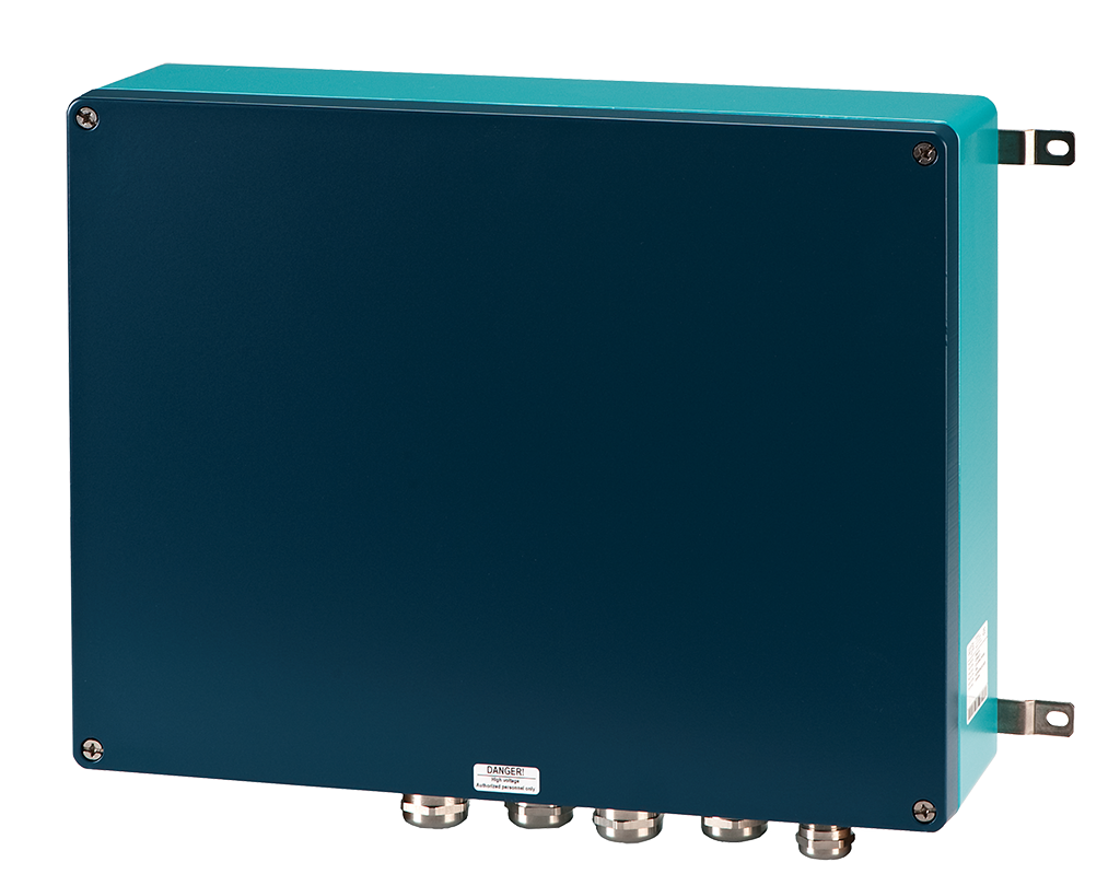
CIP400-XX
Obstruction light system controller including Ethernet connection
Controller for use with Orga obstruction light systems for on & offshore windfarm applications. The CIP400 provides full system operation management, advanced control facilities, status information, and system diagnostics through an Ethernet port.
Key features
- Controller for systems with Orga aeronautical obstruction lights, Helihoist lights, Search and Rescue, ID lights & Visibility sensors
- System status monitoring and alarm interface
- Manual Control override of connected lights
- Control options: Modbus, Webserver over TCP/IP & hard wired I/O
- Simple cable connection for easy installation
- Supplied with EMC cable glands / blind plugs
- Two year warranty
- No maintenance required over service life
Physical characteristics
- Dimensions: see drawing
- Weight: 9kg
- Design degree of protection: IP65
- Operating temperature range:
-40°C to +55°C - AlSi12 alloy painted enclosure
- Shipping information:
500x450x200 mm; 11 kg
Standards / certification
- ICAO Annex 14, volume l; International standards and recommended practices: Aerodrome design and operations, 6th Edition, July 2013, chapter 6 (for systems incl. CIP400 controllers and obstruction lights)
- United States Federal Aviation Administration AC 70/7460-1K; Obstruction Marking and Lighting, February 2007(for systems incl. CIP400 controllers and obstruction lights)
- Various national approvals (for systems incl. CIP400 controllers and obstruction lights)
Electrical characteristics
- Operating voltage: See table
- Power consumption: 1W
- Overvoltage protection: Class III according to IEC61643-1
Performance characteristics
- Controls up to ninety Orga aeronautical obstruction lights
- Ethernet interface for remote system monitoring and control
- Ethernet connection CAT6 with RJ45 connection compatible with standard IEEE 802.3u
- Overall system fail contact
- I/O interface for control using input signals
- Optional main–standby light configuration available


